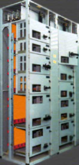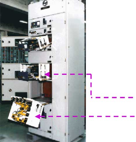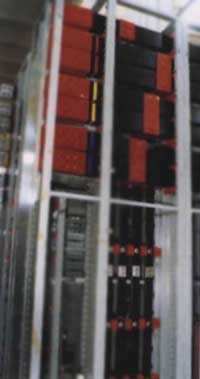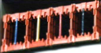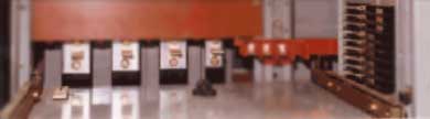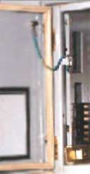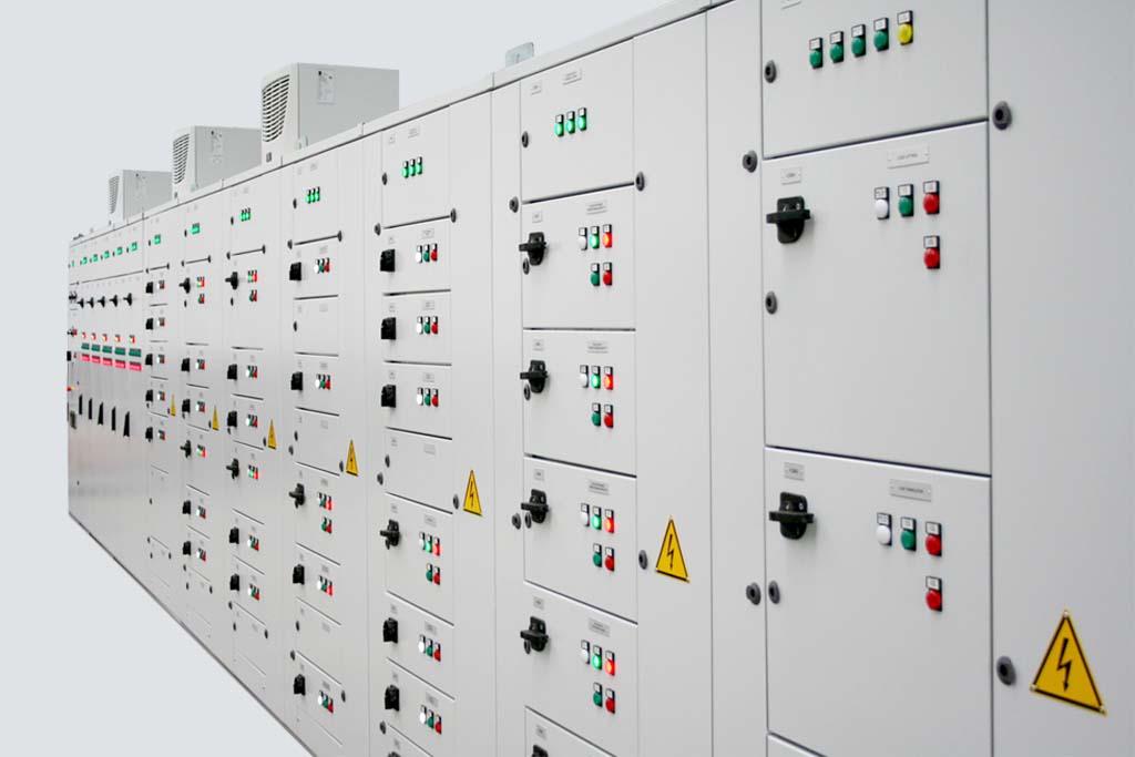
Motor Control Center
Motor Control Center are offered upto 1600 A operational current at 40 degree Celsius ambient Temperature in single and double front design for 50 kA short Circuit Withstand Capacity and IP: 52 degree of Protection. Form IV of separation as per IS: 8623 is maintained. Types of starters include Automatic Star Delta, Direct On-line, Soft Starters, Variable Frequency Drives, Stator Rotor Starters and AutoTransformer Starters.